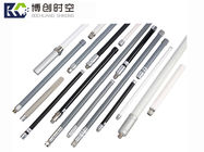
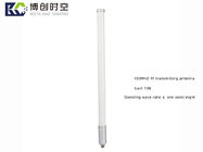
VHF Interphone Antenna 7dB high gain 433MHz wireless transmitting high frequency antenna ship communication antenna 2m
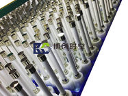
Our company Shenzhen Bochuang space-time Communication Technology Co., Ltd. is a professional manufacturer of jammers, detectors, amplifiers, RF chips, RF antenna accessories and finished products. Because there are many kinds of products, the workload of taking detailed drawings is too large and needs to be improved, so the link Title matches the first picture of the main picture. All the pictures presented in the shop are real pictures of the physical objects produced by the factory, Are available and support customization! Bochuang space-time brand, professional R & D, design and manufacturing of antenna, looking forward to cooperating with you! Please consult customer service for details!
| brand |
Bo Chuang space time |
| model |
BCSK-UHF |
| gain |
7dBi Bochuang spatiotemporal brand can be customized according to customer needs |
| frequency range |
You can customize any frequency to consult customer service |
| Article number |
FRP bcsk-hg028 |
| Output impedance |
50 Ohm |
| Standing wave ratio≤ |
1.8 |
| working voltage |
3~36V |
| Is there a special supply source for cross-border export |
yes |
| Main downstream platforms |
Independent station |
| Main sales area |
Global |
| There are authorized private brands |
YES |
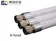
| Connector style |
N-head, SMA, FME head, etc. (customizable) |
| Specification and shape |
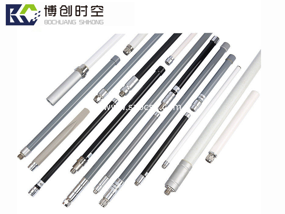
φ( 15 ~ 22) * (100 ~ 1028) mm customizable |
| Color appearance |
Black, white, gray, silver, etc. (customizable) |

产品展示PRODUCT DISPLAY
1 development history of mobile base station antenna
2 basic knowledge of electromagnetic wave propagation
Definition of radio waves
Radio wave is a form of signal and energy propagation. In the propagation process, the electric field and magnetic field are perpendicular to each other in space, and both are perpendicular to the propagation direction.
Propagation direction of radio waves
Orthogonal characteristics; Electricity generates magnetism and magnetism generates electricity.
Relationship between wavelength, frequency and propagation speed of radio wave
Where: wavelength λ= C / F (where C is the speed of light, f is the working frequency, λ Is the wavelength.)
In the same medium, the working wavelength of the antenna is different at different frequencies. The higher the frequency, the shorter the wavelength.
The electrical performance of the antenna corresponds to the electrical length (wavelength). Physical length needs to be converted.
Polarization of radio waves
When a radio wave propagates in space, its electric field direction changes according to a certain law. This phenomenon is called radio wave polarization. The polarization of radio wave is determined by the trajectory of electric field vector in space. If the electric field direction of a radio wave is perpendicular to the ground, we call it a vertically polarized wave. If the electric field direction of the electric wave is parallel to the ground, it is called horizontally polarized wave.
Circular polarization < - elliptical polarization = "" - = "> linear polarization
Left and right rotation; Vertical and horizontal
Antenna polarization
It refers to the trajectory of the electric field vector in space.
Dual polarization antenna
It is composed of two groups of orthogonal radiation units.
1) Complementary (complete) unrelated. Orthogonality / 90 degrees) (planning work)
2) Fairly balanced work+ 45 / - 45) (competent)
3) High efficiency (XPD reduces loss) (focus on work)
Multipath propagation
In the process of radio wave propagation, in addition to direct propagation, it will also produce reflection and diffraction when encountering obstacles (such as hills, forests, ground or buildings and other tall buildings). Therefore, the electromagnetic wave reaching the receiving antenna includes not only direct wave, but also reflected wave, diffracted wave and transmitted wave. This phenomenon is called multipath transmission.
Due to multipath propagation, the signal field strength distribution is complex and fluctuates greatly; Due to the influence of multipath transmission, the polarization direction of radio waves will change (twist). Therefore, the signal field strength will increase in some places and decrease in some places. In addition, the reflection ability of different obstacles to radio waves is also different. In order to reduce the influence of multipath transmission effect, spatial diversity or polarization diversity is generally used to receive.
Spatial diversity: monopolar antenna
Polarization diversity: dual polarization antenna
3 antenna radiation principle
Definition of antenna
A device that can effectively radiate electromagnetic waves in a specific direction of space or effectively receive electromagnetic waves from a specific direction of space.
Antenna half wave oscillator
The half wave oscillator is the basic radiation unit of the antenna. The longer the wavelength, the larger the half wave oscillator of the antenna.
Example of half wave oscillator:
Antenna radiation pattern
It is used to describe the ability of the antenna to transmit and receive electromagnetic waves in all directions of space. Generally, it is a three-dimensional radiation stereogram.
In the actual evaluation, it is transformed into two-dimensional plane graphics, namely water plane pattern and vertical plane pattern.
Antenna components
The same base station antenna has a variety of design schemes. The design scheme involves the following four parts of the antenna:
1) Radiating element (symmetrical oscillator or patch [array element])
2) Reflector (base plate)
3) Power distribution network (feeder network)
4) Package protection (radome)
4 main performance parameters of antenna
Antenna operating frequency
No matter the antenna or other communication products, they always work within a certain frequency range (bandwidth), which depends on the requirements of the index. Generally, the frequency range meeting the index requirements can be the working frequency of the antenna.
Generally speaking, the antenna performance is different at each frequency point within the working band width. Therefore, under the same index requirements, the wider the working frequency band, the greater the difficulty of antenna design.
Radiation parameters
Main valve;
Accessory valve;
Half power beam width;
Gain;
Beam dip angle;
Front to back ratio;
Cross polarization discrimination rate;
Upper sidelobe suppression;
Lower zero filling;
According to the influence of antenna radiation parameters on network performance, it can be classified as follows:
Half power beam width
Within the main lobe of the pattern, the angular domain width when the relative maximum radiation direction power density decreases to half, also known as 3dB beam width.
The horizontal half power beam width is called the horizontal beam width; The half power beam width of the vertical plane is called the vertical beam width.
Relationship between antenna gain and beam width:
Horizontal beam width
The antenna of each sector reaches the coverage edge when the maximum radiation direction deviates by ± 60o, and needs to be switched to adjacent sectors. There should be a reasonable drop in the pattern level in the switching angle domain of ± 60o. When the level drops too much, it is easy to cause a call drop in the coverage blind area near the switching angle domain; When the level drops too little, the coverage overlaps near the switching angle domain, resulting in increased interference of adjacent sectors.
The results of theoretical simulation and practical application show that in the urban area with dense buildings, due to the serious multipath reflection, in order to reduce the mutual interference between adjacent sectors, it is better to reduce the level of ± 60o to about - 10dB, and the width of reverse half power is about 65o; In the open suburbs, due to less multipath reflection, in order to ensure good coverage, it is better to reduce the level of ± 60o to about - 6dB, and the reverse half power width is about 90o.
The horizontal beam width, beam deflection and pattern consistency determine the azimuth performance of the coverage area.
Multipath reflection propagation:
P ~~ 1/R^n
n = 2~4
± 60o level design:
------------------
Urban area n = 3 ~ 3.5
9 ~ 10.5db drop
Country: n = 2
6 dB drop
Vertical beam width and electric dip angle accuracy
It determines the distance performance in the network coverage area.
Observe the vertical plane pattern in the following figure. The beam should be properly tilted downward, and the downward angle should preferably make the maximum radiation point to the edge of the target service area in the figure. If the dip is too much (yellow), the coverage level at the far end of the service area will drop sharply; If the downward tilt is too small, it will cover outside the service area and cause the same frequency interference problem.
Electric dip angle
The angle between the maximum radiation direction and the antenna normal.
Fore-and-aft ratio
It is an important index to suppress co - channel interference or pilot pollution
Generally, it is only necessary to investigate the front to back ratio of the horizontal plane pattern, especially the worst value within the backward ± 30 °.
The worse the front to back ratio index, the greater the backward radiation, and the greater the possibility of interference to the coverage cell behind the antenna.
In special applications, the front to back ratio of the vertical plane pattern will be investigated. For example, there are super high-rise buildings in the back area of the base station.
Antenna gain
It refers to the ratio of the radiated power flux density of the antenna in a specified direction to the maximum radiated power flux density of the reference antenna (usually using an ideal point source) at the same input power.
Relationship between antenna gain, pattern and antenna size
Antenna gain is used to measure the ability of antenna to transmit and receive signals in a specific direction. It is one of the important parameters for selecting base station antenna.
The higher the antenna gain, the better the directivity, the more concentrated the energy and the narrower the lobe.
The higher the gain, the longer the antenna length.
Several key points of antenna gain:
1) The antenna is a passive component and cannot generate energy. Antenna gain is only the ability to effectively concentrate energy to radiate or receive electromagnetic waves in a specific direction.
2) The gain of the antenna is generated by the superposition of oscillators. The higher the gain, the longer the antenna length.
3) The higher the antenna gain, the better the directivity, the more concentrated the energy and the narrower the lobe.
The gain affects the coverage distance index. Select the gain reasonably!!!
Increasing the antenna gain will increase the coverage distance, but at the same time, it will narrow the beam width, resulting in poor coverage uniformity. The selection of antenna gain shall be based on the matching of beam and target area. In order to improve the gain, it is not advisable to excessively narrow the beam width of vertical plane. Only through the optimization scheme, can the level outside the service area drop rapidly, reduce the side lobe and back lobe, reduce the cross polarization level, and adopt low loss, no surface wave parasitic radiation Low VSWR feed network and other ways to improve antenna gain are correct.
Cross polarization ratio
Index of polarization diversity effect
In order to obtain good uplink diversity gain, the dual polarization antenna shall have good orthogonal polarization characteristics, that is, in the sector service area of ± 60o, the cross polarization pattern level shall be significantly lower than the main polarization level at the corresponding angle, and the difference (cross polarization ratio) shall be 15dB greater in the maximum radiation direction and 10dB greater in ± 60o, The minimum threshold should also be greater than 7dB, as shown in the figure. In this way, it can be considered that the signals received by the two polarizations are not related to each other.
Sidelobe suppression
Auxiliary index for suppressing co frequency interference or pilot pollution
For the application scenarios with dense buildings in urban areas, on the one hand, due to the large communication capacity, it is required to reduce the cell, on the other hand, it is difficult to achieve long-distance coverage due to building occlusion and multipath reflection. Generally, a low gain antenna with a gain of 13 ~ 15dbi and a large downdip angle are used for micro cellular coverage. Therefore, it is very possible for the upper first and second sidelobes of the main beam to point to the front same frequency cell, which requires that when designing the antenna, try to suppress the upper sidelobe to reduce interference.
Lower zero filling
In some special scenes, the auxiliary index to reduce blind spots is limited
In antenna design, if the lower zero point is properly filled, the call drop rate may be reduced. However, zero filling should be enough. When the requirement for zero filling is high, the gain loss is large and the gain is not worth the loss. For low gain antennas, due to the wide lobe, the downward inclination is usually large, the lower sidelobe does not participate in the coverage, and zero filling is not required.
Due to the influence of multipath, the near zero effect is not obvious or disappears.
Pattern roundness
Index for evaluating uniform coverage effect of omnidirectional antenna
Only the roundness of the horizontal pattern needs to be investigated. Evaluation example: the index is ± 1dB, and all frequency points need to be better than this index.
Voltage standing wave ratio
Voltage standing wave ratio (VSWR): the ratio of the maximum voltage to the minimum voltage on the transmission line.
When there is no reflection at the antenna port, it is an ideal match, and the standing wave ratio is 1; When the antenna port is fully reflected, the standing wave ratio is infinite.
Voltage standing wave ratio (VSWR) is the basic requirement of antenna high efficiency radiation.
Investigate VSWR in the whole frequency band and take the maximum value as the index.
Evaluation example: the index is 1.5, and all frequency points need to be better than this index.
Isolation degree
It refers to the proportion of another polarization signal received by one polarization.
It generally refers to the direct isolation of two polarizations in a dual polarization antenna.
Third order intermodulation
Ensure that the intermodulation interference transmitted by the antenna does not affect the sensitivity of the receiver
Investigate PIM3 in the whole frequency band and take the maximum value as the index.
It can reflect the comprehensive level of the supplier's antenna products, especially the quality control ability of material production and assembly process.
Necessary conditions for intermodulation interference: strong enough intermodulation signal level + can fall into the system receiving frequency band
Measurement unit of main parameters of antenna
Description of UOM
1) dB
Relative value, which represents the relative size relationship between two quantities. For example, the power of a is larger or smaller than that of B
The number of DB can be calculated as 10log (a power value / B power value).
For example, the power value of a is 2W and the power value of B is 1W, that is, a is twice as much as B, which is converted into DB unit:
10log(2W/1W) ≈3dB
2) dBm
The quantity characterizing the absolute value of power can also be considered as a ratio based on 1MW power, which is calculated as 10log (power value / 1MW).
For example, the power value is 10W, which is converted to 10log (10W / 1MW) = 40dbm.
3) DBI and DBD
Both represent the amount of antenna gain, which is also a relative value. It is similar to DB, but DBI and DBD have fixed reference standards: the reference standard of DBI is an omnidirectional ideal point source, and the reference standard of DBD is a half wave oscillator.
Example: 0dbd = 2.15dbi.
5 future of antenna technology
High performance antenna
Facing the increasing traffic demand, antenna technology is the key to improve network capacity. Since the capacity is limited by SINR, to improve SINR through antenna technology, it is necessary to minimize inter sector interference and maximize and concentrate antenna radiation energy.
Multi beam antenna technology
Use multi beam antenna to split sectors to improve capacity, such as 2 x 9 x 6 ° 18 beam antenna.
RF part and antenna fusion
Source: the middle part of this article is from Jingxin communication (Wang Xiaoyang), and the full text is from the electronic engineering album